================================================================================================================================================

Wednesday, January 26, 2022

String and File Encryption with AES - Code Testing on Raspberry Pi Pico


On this page:

Introduction

    Data Encryption has become an absolute necessity in today's world of internet. In embedded systems also, it has become an integrated part due to the wide spread of IoT and other online systems. Sometimes we also need files to be encrypted on local storage like built-in flash or memory cards, etc. to protect certain information. There are various algorithms to encrypt files. Here, we are going to compare some library implementation examples of the most used standard today, AES. 

    The Advance Encryption Standard (AES) is a block cipher, which uses 128 or 192 or 256 bit key to encrypt or decrypt 128 bit (16 byte) block of input data. So, the input file (or data string) is processed in blocks of 16 bytes each, as per the Block Cipher mode of operation (see the wiki here). In addition, based on the mode of operation, Initialization Vector (IV) is also required for AES, which is unique (usually generated run time) for each encryption operation.

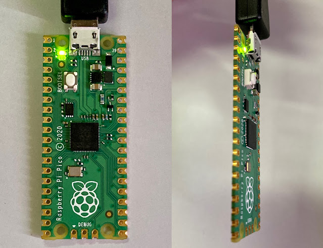
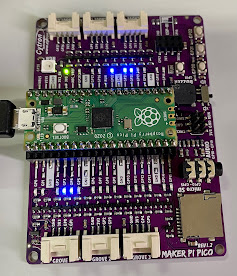
    I was checking out some libraries to use for file encryption in a project. So, I decided to test them mainly for the speed of encryption/ decryption, which is the subject of this post. The resultant test codes with terminal outputs are given here. These may serve purpose of example/ demo code for newcomers interested in checking out AES functionality in their programs. For testing these code examples, only hardware required is a Raspberry Pi Pico board and the USB programming cable, and you are ready to go with a laptop/PC loaded with IDE (PlatformIO or Arduino).

    Here, I'm comparing four AES libraries, tested on Raspberry Pi Pico, to check out mainly the speed and code size for the implementation. These four libraries are:


    1. Mbed AES Lib, by Neil Thiessen
    2. Arduino AES Lib, by Matej Sychra
    3. MbedTLS Lib, by ARMmbed
    4. tiny-AES-c Lib, by kokke

    All these libraries are tested here using almost same main code, with same input character string (plain text), same key and same IV. 128-bit and 256-bit AES (CBC mode) testing is done for all libraries. The key in the code is kept 256 bit long, so that the 128/192/256 AES can be selected just by changing a macro in the file. The encryption and decryption times are measured and displayed on terminal.
    Please note that these key and IV are only for the testing only, not for practical usage. In reality, usually the key is secret and IV is different for each string/file.
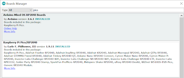
    The codes are tested in PlatformIO IDE, Raspberry Pi Pico-Arduino platform, which is the Arduino-Mbed package. These codes can be run in Arduino IDE as well, selecting the "Arduino Mbed OS RP2040 Board" in the board manager. The codes can be easily adopted to any other 32bit controller/IDE as well with minimum modifications.

Note: For PlatformIO, create new project and copy the downloaded files (from .zip) into the project folder. In Arduino, use main.cpp as a sketch (after renaming with .ino extension) and put the library files into the library folder of your arduino sketchbook and ignore the platformio.ini file.


Case 1: Mbed AES Lib (by Neil Thiessen)

    This library is posted in the Mbed repository, as a light-weight AES implementation with Cipher Block Chaining and Ciphertext Stealing (url: https://os.mbed.com/users/neilt6/code/AES/). 
(I had done minor modifications, mainly defining char as uint8_t, in the variable/function declarations to remove some compiler errors/warnings, during earlier testing on Mbed-Studio IDE. The same files have been used here). 
    (AES-128/192/256 option is selected here by setting AES::KEY_XXX, where XXX is the 128/192/256, in the arguments of the function aes.setup(), before encrypt and decrypt functions)

Code (aesTest1):


Results

Compiler Output:
RAM: [== ] 15.2% (used 41076 bytes from 270336 bytes) Flash: [ ] 0.2% (used 4134 bytes from 2097152 bytes)

Terminal Output (AES-128):
INPUT: AES_Test_1 - Hello! Testing AES Encryption here Cipher Text: D56B041BF7AEEA37818A98F224F38376ECB83D9F56A3354A64DFFA05D87704F7E4B86DF2E64197B66843BE995B Encryption Time (us): 1305 Plain Text: AES_Test_1 - Hello! Testing AES Encryption here Decryption Time (us): 2337 SUCCESS

Terminal Output (AES-256):
INPUT: AES_Test_1 - Hello! Testing AES Encryption here Cipher Text: ACAC7D235752782F65C4C9ABB5AA5BD60D2B5DECDD0E94035CA2B49785C295132885FD282A96C32C7A95184931ED4E Encryption Time (us): 1842 Plain Text: AES_Test_1 - Hello! Testing AES Encryption here Decryption Time (us): 3338 SUCCESS

Download Code files:
  • aesTest1.zip (main.cpp, AES_lib.cpp, AES_lib.h and platformio.ini)    

Case 2: Arduino AESLib Library (by Matej Sychra)

     This library is part of Arduino libraries (AESLib - Arduino Reference), as an ESP32/ESP8266 library for Arduino IDE to wrap AES encryption with Base64 support. This works on Pi Pico as well. Repository url is: https://github.com/suculent/thinx-aes-lib. The library files are used as downloaded without any changes.
     (AES-128/192/256 option is selected here by setting AES_XXX, where XXX is the 128/192/256, in the arguments of the function calls aesLib.encrypt64() and aesLib.decrypt64(). Appropriate macros are already defined at the top part of the code).

Code (aesTest2):


Results

Compiler Output:
RAM: [== ] 17.4% (used 47100 bytes from 270336 bytes) Flash: [ ] 0.2% (used 4546 bytes from 2097152 bytes)

Terminal Output (AES-128):
INPUT: AES_Test_2 - Hello! Testing AES Encryption here Cipher Text: 6368354D2F51637A744E694D7A344D4B4F67382B6230467A58752F53624636516979577A6371756C7A545430344E422B41747A5861364D6E5370774962452F766A356663575369335576645A794B765562795372337366455A78484856754F59674D5167736E4674372B6B3D Encryption Time (us): 456 Plain Text: AES_Test_2 - Hello! Testing AES Encryption here Decryption Time (us): 820 SUCCESS

Terminal Output (AES-256):
INPUT: AES_Test_2 - Hello! Testing AES Encryption here Cipher Text: 43304A6C774347356D7745484D3534666D4537792B6F4132494342354858734C724C5663705645666D36772B6F677058736C4A474374767973694A6C714E5961546F375532476737516752376936364861683557783173364C746243726E41757130334546622F38725A303D Encryption Time (us): 604 Plain Text: AES_Test_2 - Hello! Testing AES Encryption here Decryption Time (us): 1093 SUCCESS

Download Code files:
  • aesTest2.zip (main.cpp, AESLib library folder and platformio.ini) 

Case 3: MbedTLS Library (by ARMmbed)

     Mbed TLS is a C library that implements cryptographic primitives, X.509 certificate manipulation and the SSL/TLS and DTLS protocols. Its small code footprint makes it suitable for embedded systems. (Ref: https://github.com/ARMmbed/mbedtls). We are using here only the AES functions of this library. As this library is part of the Mbed-OS, no need to separately download/add, we just need to include the relevant file in the code and call the functions.
     (AES-128/192/256 option is selected here by setting AES_XXX, where XXX is the 128/192/256, in the arguments of the function calls mbedtls_aes_setkey_enc() and mbedtls_aes_setkey_dec(). Appropriate macros are already defined at the top part of the code). 

Code (aesTest3):


Results

Compiler Output:
RAM: [== ] 15.3% (used 41320 bytes from 270336 bytes) Flash: [ ] 0.2% (used 4082 bytes from 2097152 bytes)

Terminal Output (AES-128):
INPUT: AES_Test_3 - Hello! Testing AES Encryption here Cipher Text: FB934B82E7CA12EAD35C017948AB881A3CEAB6A58C1BED4B2C1CF6D9B79F2EF691488A1E98D6F36CB51EE15F0FFAE42 Encryption Time (us): 170 Plain Text: AES_Test_3 - Hello! Testing AES Encryption here Decryption Time (us): 161 SUCCESS

Terminal Output (AES-256):
INPUT: AES_Test_3 - Hello! Testing AES Encryption here Cipher Text: 22BFF69B724C3F5CCDCA0D930823F2662ED857E0F1617808AAEA51F7592E6B3F72B262D801AF52FE4911B3B2B Encryption Time (us): 215 Plain Text: AES_Test_3 - Hello! Testing AES Encryption here Decryption Time (us): 207 SUCCESS


Download Code files:
(Note: While testing in Arduino IDE, if you are not using"Arduino Mbed OS RP2040 Board" in the board manager, you will need to download the mbedtls library as well and put it in the library folder for this code to work).

Case 4: tiny-AES Library (by kokke)

    This is a small and portable implementation of the AES ECBCTR and CBC encryption algorithms written in C (Ref: https://github.com/kokke/tiny-AES-c). 
      (AES-128/192/256 option is selected here by defining the symbols AES128 or AES192 or AES256 inaes.h. Default setting AES128 is already defined there.

Code (aesTest4):


Results

Compiler Output:
RAM: [== ] 15.1% (used 41000 bytes from 270336 bytes) Flash: [ ] 0.2% (used 4082 bytes from 2097152 bytes)

Terminal Output (AES-128):
INPUT: AES_Test_4 - Hello! Testing AES Encryption here Cipher Text: 997E26867A8D10145EDA12F1FBBE45B2794929C45E2086F6172801AB0ABE711AEE0EBF548A958B928E851BF96E5A4 Encryption Time (us): 246 Plain Text: AES_Test_4 - Hello! Testing AES Encryption here Decryption Time (us): 463 SUCCESS

Terminal Output (AES-256):
INPUT: AES_Test_4 - Hello! Testing AES Encryption here Cipher Text: 2461EC62971158335F198DE6A3478E9B459A1AED7BFF647BAAF031B132EF094BE4C9B3EEA2177D52858FF329ED7662 Encryption Time (us): 345 Plain Text: AES_Test_4 - Hello! Testing AES Encryption here Decryption Time (us): 622 SUCCESS


Download Code files:
  • aesTest4.zip (main.cpp, tiny-AES library folder and platformio.ini) 


Sr.

No.

Library

AES-128 Time (µs)

AES-256 Time (µs)

Pi-Pico Usage (KB)

Encrypt

Decrypt

Encrypt

Decrypt

RAM

FLASH

1.

Mbed AES lib,

by Neil T.

1305

2337

1842

3338

41.076

4.134

2.

Arduino AESLib,

by Matej S.

456

820

604

1093

47.100

4.546

3.

MbedTLS,

by ARMmbed

170

161

215

207

41.320

4.082

4.

tiny-AES,

by kokke

246

463

345

622

41.000

4.082


    From the above comparison, it is clearly seen that the No.3, MbedTLS AES, is fastest among all the four. Flash and RAM consumption is also low. (Note: In these examples, major chunk of RAM, >40KB, is occupied by the background processes of Mbed OS itself).
    MbedTLS is also feature-rich, when you go further into encryption, for applications like IoT. It's a good library to practice with, for future expansion of the hobby projects. Considering that, I'm also adding here an example of encrypting/ decrypting a file using MbedTLS functions.


    Here, we're going to encrypt and decrypt a small file from the on-board Flash memory of Pi Pico. LittleFileSystem and BlockDevice (FlashIAPBlockDevice) libraries built into the Mbed-OS are used here for creating and accessing the files. As onboard memory is used, no extra component is required apart from Pi Pico + Programming cable setup used in the above AES examples. 
    The file encryption/ decryption function (fileAES()) is adopted from the main() function of crypt_and_hash.c file of mbedtls library. 

    While encrypting, this function reads the input file (plain text) and AES key, generates Initialization Vector (IV), then hashes the IV and AES key together to setup AES context and generate HMAC (Hash Message Authentication Code). Then it carries out encryption (cipher update) block-by-block (block size: 128 bits/16 bytes). The output file (named here as cipherFile.aes) is created in the format: 
    Output File: IV (16 bytes) + encrypted file blocks + HMAC/Hash (64 bytes)

    While decrypting, the cipher file is input along with the AES key, the IV is read from cipher file, the hashing is done similar to as done during encryption, then decryption is carried out block-by-block, and finally the Hash is compared with what is stored in the cipher file to confirm the validity of decrypted output file. 
    The AES key is declared in the main.cpp file for the demo purpose, not for use in actual project. A fixed text string is used repeatedly for creating the input file. These can be modified in the main.cpp.

Code (littleFsAes):

    Following is the main file where filesystem is mounted and input (with data to be ecrypted), cipher (empty) and output(empty) files are created. After creating these files, the fileAES function is called with arguments for encryption and then decryption. The time is measured in miliseconds to display on terminal. The file system used here is LittleFileSystem from Mbed-OS. The input and output files can be printed on terminal by enabling the relevant commented out section of the code.

main.cpp


Following is the header file for using with fileAES.cpp.

fileAES.h


    Following is the fileAES.cpp file where fileAES() function is implemented. This file is originally taken from MbedTLS library, crypt_and_hash.c. Minor modifications are done to convert existing main() function in it into fileAES() function, which is called from main() function given above. As file access functions of the original file are same in LittleFS as well, modifications are minimum. 

fileAES.cpp

Results

Compiler Output:
RAM: [== ] 15.3% (used 41380 bytes from 270336 bytes) Flash: [ ] 0.2% (used 4534 bytes from 2097152 bytes)

Terminal Output (Input File with 10 lines, 630 Bytes):
AES File Encryption (using Mbedtls) on Raspberry Pi Pico (mbed-arduino) Flash BD Initialized! FileSystem mounted! File Size (W): 630 Encryption Done, Time taken: 2343 ms Decryption Done, Time taken: 2338 ms Example Done!

Terminal Output  (Input File with 100 lines, 6300 Bytes):
AES File Encryption (using Mbedtls) on Raspberry Pi Pico (mbed-arduino) Flash BD Initialized! FileSystem mounted! File Size (W): 6300 Encryption Done, Time taken: 2425 ms Decryption Done, Time taken: 2429 ms Example Done!

    File size here is in Bytes. The increased file size does not increase the time significantly for small file size, as the AES context setup part dominates the time taken  as compared to the time taken in encryption/ decryption. Also, the Flash memory is faster. When the file is stored in external memory devices like SD card, the serial interface speed as well as the device library being used affect the encryption/ decryption time w.r.t. change in the file size. 

Download Code files:

    If you have more jobs to be done which are time critical, the time consuming job of file encryption/ decryption can be given to the second core of Pi Pico, which will significantly free up the first core. In my future post, I'll add the code examples for file encryption on SD cards as well as the multicore implementation.

Happy coding!

Sunday, January 9, 2022

Raspberry Pi Pico - A Tiny Power-Packed Development Board


Raspberry Pi Pico is a relatively new, tiny but powerful development board designed by the Raspberry Pi (UK), which is based upon RP2040 microcontroller chip, developed in-house by Raspberry Pi. The microcontroller has dual-core Arm Cortex- M0+ Processor, running at clock up to 133MHz, with 264KB internal RAM and supports up to 16MB of external Flash. Multicore operation is supported by a pair of four entry FIFOs (one in each direction between the cores).

The Pi Pico board has 2MB of on-board QSPI Flash, which is programmable through USB Mass Storage Device mode or using Serial Wire Debug port. It also features wide range of flexible I/Os, like GPIO, UART, I2C, SPI, USB and also Programmable I/O (PIO), which is unique to this board. The board has small footprint with solderable headers. It is very cost-effective, available from large number of vendors, may be available in your nearest electronic shop, too. This opens doors for utilization towards a wide range of applications for novices as well as experts.

Detailed information on Raspberry Pi Pico is available here:

Following image with Pin-diagram of Pi Pico gives idea about various I/Os of the device: (courtesy- Raspberry Pi website):


The Pi Pico can be programmed in C/C++ (SDK support is provided by Raspberry Pi), Arduino or MicroPython. A lot of resources have already been made available in such a short time, for this board. That actually shows the rapid growth of interest in Pi Pico and usage by hobbyists/ professionals together. New libraries, packages and platform supports are getting added at quite a fast pace.

I've liked this board so much that I'm literally hooked to it 😊. The purpose of my this post is just to put up an introduction with resource pointers, which I wanted to do for quite some time, before I start posting experimental codes also, using it.


The Pico-SDK: This is official SDK from Raspberry Pi team, for writing C/C++ or assembly language code for Pi Pico, full with headers, libraries and build system, designed to provide an API and programming environment. Multicore support examples are also given.

Pico-SDK GitHub page provides detailed description and links for documentation for using the SDK projects. The SDK can be easily setup with VS Code for programming the Pi Pico. It also has the example projects to demonstrate the use of SDK for various peripherals/ interfaces of the device.

(You can also visit the wizio-pico project page on github, for faster way of getting started with installation and usage of pico-sdk on PlatformIO with VS Code)


The Pico-Arduino: The addition of the Arduino support has made Pi Pico even more easier to use for any newcomer who wants to get hands-on experience with it. 

There are two packages, shown in Arduino Boards Manager, "Arduino Mbed OS RP2040 Boards" and "Raspberry Pi Pico/RP2040" as shown here:


Both these board support Pico-SDK functions also. Raspberry Pi Pico/RP2040 GitHub page shows detailed information on installation and usage of the package with Arduino. Arduino Pico Document  provides detailed information on writing the code, with examples. This document by Earle F. Philhower, III, is getting updated, like, every other day! :)  This board also supports multicore programming using additional setup() and loop() functions (named setup1() and loop1()).

The  Arduino Mbed OS RP2040 Boards package supports Pico with Mbed RTOS for Arduino. This is really powerful. The Mbed OS is already being used widely in ARM Cortex devices, and support for the same in Pico Arduino makes things even more versatile and mighty by providing access to the various Mbed APIs inside Arduino.

With PlatformIO for VS Code: PlatformIO is a powerful IDE, which can be used for Pi Pico Arduino. The "Raspberry Pi Pico" board is shown in the Board Explorer of PlatformIO home menu. This is same as "Arduino Mbed OS RP2040 Boards" in Arduino IDE. The platfomIO provides professional features of code editing, auto code-completion suggestions / intelliSense, debug options, etc., which are not available currently in Arduino IDE.

Both the above Arduino packages have different default pin assignments for I2C, SPI, etc. Hence, interchangeability of the code has to be properly checked before changing the board setting. As lot of work is currently going on, I suppose there will be a single combined package in the future, which will do away with some of the initial confusion while programming.


Pi Pico with MicroPython: Pi Pico can also be used with MicroPython (or CircuitPython) interpreters, which make programming still easier for newbies who want to avid C/C++, or for programmers already experienced in Python.

Micropython.org page for Pi-Pico provides quick-start reference on installation and usage of micropython on Pi Pico. Also, Raspberry Pi official Datasheet of Python SDK is filled with detailed info on coding with micropython, with examples. This GitHub page also provides ready to use examples in micropython.

Thonny is easy to use, light-weight Python IDE for beginners. The Raspberry Pi page here provides getting started with micropython using Thonny IDE. The Adafruit page provides details on configuring Thonny with CircuitPython for Pi Pico.


Supporting Base Boards: Raspberry Pi Pico is easy to use on breadboard itself for initial prototyping or testing work, great for hobbyists. But if you need some proto board with ready connections for experiments, the Maker Pi Pico Base board looks great. It has got LEDs already mounted on each GPIO pin, providing visual feedback on the code functioning. It has also got other peripherals like microSD card, buzzer (speaker), audio jack, pushbuttons and also connector for ESP32 device for adding WiFi to the project. It's also available online, I think at most places. Here is my board:


You can also opt for a simple GPIO extension boards, like these:


These board are available on amazon, needs to just search for Pi Pico. You'll also get these or similar easily from your local suppliers, too. (In my recent experience during the chip shortage period, I've found getting Pi Pico boards far easier than many other development boards. That's one more incentive to use them!)

Summary:

I hope this gives you the idea of how easy it is to get started with Pi Pico board. The board is really cute, beautifully manufactured! Once you hold it in your hand, may be you'll fall in love with it, too!!😊 Small and yet, it is so powerful for such a size! Go ahead and grab one, you won't regret it.! 👍


Further Reading/ References:

  1. Raspberry Pi Pico Getting Started (Intro to setting up development environment, programming and loading the code into the board)
  2. RP2040 Microcontroller Datasheet (device datasheet of the chip itself)
  3. Pi Pico Board Datasheet (Pico board details with electrical, mechanical specs, powering, components, schematics and application briefs)
  4. Pi Pico Pinout (Pinout with alternative functions)
  5. Pi Pico Hardware Design Reference (Must read before you go ahead with making more hardware connections, other than blinking LEDs!)
  6. Pi Pico C/C++ SDK (C/C++ API function/interface details)
  7. Pi Pico Python SDK  (Python API function/interface details)
  8. Pico-SDK Documentation (doxygen)
  9. Arduino Pico documentation (details of Arduino API implementation)
  10. MicroPython Quick Reference for Pi Pico
  11. Beginner's Guide for R-Pi Pico (A nice starting guide with hardware setup and programming in MicroPython, from seeedstudio.com)

    You can also check out my next post on Raspberry Pi Pico with AES encryption example codes.

Wednesday, July 4, 2018

UART or SD Card based 8-Channel Data-logger with temperature log


Hi Friends,
        here is one more data-logger circuit, which will be useful for some who have not much ventured into the ADC for datalogging or RTC or i2c communication, etc. This one is based on ATmega32. It has 8-channel 10-bit ADC. Hence, providing us with 8-channels with 0 to 5V voltage level measurement. The circuit also has on-board RTC (based on DS1307) to log the data with time-stamp. Data is logged via UART or using microSD card. The circuit has 3-pin UART connector, which can be used to connect to PC/laptop using UART(TTL) to USB serial converter, commonly available in electronic markets (UART setting: 38400-1-N-1).
      Also, there is a thermometer IC, DS1621, which is connected via i2c (along with the RTC IC) and provides temperature measurement from -55 to +125 Deg. C. The temperature is also sent along with the voltages to the UART for logging.
     (The logging with microSD card is added later in this post).
    The circuit schematic is given in the following figure (pdf file can be downloaded from here):


     At power on, the current date and time are displayed on the first raw of LCD. The temperature and the logging ON/OF status is displayed on the second raw. A green LED is also turned ON as an additional status of the proper power-up of the microcontroller .
     The data measurement can be started anytime by pressing the 'SET' button (keep pressed till the red LED turns ON). The recording ON status is displayed on LCD as well as by the glowing red LED. During this recording, at a regular interval (as defined in the code), the microcontroller gets the temperature from DS1621, measures the 8 voltages connected to 8 of its screw-terminals, w.r.t GND on the 9th terminal (as shown in the schematic), and forms a string which includes line number, time (hh:mm:ss format), temperature and the 8 voltage values, in a comma separated format. This string is then sent to UART, which can be logged into a file or seen on a terminal program in the PC/laptop using the serial-to-usb converter.
     The operation is shown in the following screen-shot of the Proteus simulation (in the simulation, the temperature set in the IC and displayed by the LCD has difference of 1.5C, as the code applies the correction factors read from the IC to the temperature reading and then displays it, which represents the actual temperature):


     (Note: The Proteus simulation files are included in the source code folder download at the end of the post).
   
     The circuit in operation, with logging ON and OFF, is shown the following pics:


        The actual UART output captured on a terminal of the Atmel Studio during the logging ON,  is shown in the left side image, where temperature shown is 30.3 C, channel-2 was connected with +5V (VCC) and channel-7 was connected with the Li battery cell of the RTC. Rest of the channels were kept open at the screw-terminals.

      The RTC date and time can be changed using the three push-buttons, similar to the procedure shown in my previous post of the RTC based relay-control. The procedure is given here:


For setting RTC Date/Time:

  1. Press 'SET' button and Power ON the circuit, keeping the button pressed while the circuit is starting.
  2. "RTC Setting.." message will be displayed on the first row of the LCD.
  3.  Release the 'SET' button "Date: XX" will be displayed on the second row of the LCD, where XX is the existing current date as per the RTC.
  4.  Press 'UP' or 'DOWN' button to increase or decrease the Date. When desired date is displayed, press 'SET' button to store it
  5. "Month: XX" message will be displayed, where XX is the current month as per the RTC
  6. Press 'UP' or 'DOWN' button to increase or decrease the Month. When desired month is displayed, press 'SET' button to store it
  7. "Year: XXXX" will be displayed, use 'UP'/ 'DOWN' buttons to change the year and then press 'SET' button to store the year value
  8. Then "Hour: XX" will be displayed, set it as per the previous steps and also set next "Minutes: XX" similarly, and store using 'SET' button.
  9. When the Minutes is set, "RTC Setting" mode is over and normal operation resumes, where the LCD will display Date and time in the first row and temperature and log:OFF status in the second row.


  • Data-logging with SD card 

         (Updated: Sep 2021)


Above image shows the logging with microSD card. A commonly available microSD card module (mostly used with Arduino) is used here. Please note that this module interferes with programming of the board on AVRISP port (which is not a problem with Arduino as it uses the USB bootloader programming and not AVRISP), so it's necessary to remove the card while loading the code. You can find solutions/modules online to overcome this issue.

Following images show the generated .csv file in the SD card and also opened file in MS-Excel. The logging was done without any voltages connected to the ADC channels, so the voltages are 0, but the  temperature log can be seen along with the time stamp. You can view another log file here, where I've connected the 8 channels to 3V RTC battery and VCC (~5V) line one by one (cross-coupling of signal to nearby free channel is also logged there).


The file name format is: DDMMYYNN.CSV, where DDMMYY is the date of logging and NN is the file number. After power on, the file number is set to 00. Every time logging is started and then stopped, the file number increments, hence, new file is created. As file number is a 2 digit value, max 100 (00 to 99) log files can be created after power on in a day, after that it will send error message. I guess you may not need to do the logging ON and OFF more than 100 times a day (after single power ON), but if you do, the file name string can be tweaks as necessary.

After Power off and on, when datalogging is started, the code looks if the filename is already existing or not, if it is, it will change the log-file number (and hence, name) to next available number, and so on. So, always a new file is created whenever logging is started.

  • SD card datalogging using FatFS library

I'm  also uploading here the data-logging project code with a more generic FatFs library, which has been highly standardized and is officially supported/included by many IDEs/ Development boards/ Platforms (like Arduino, mbed, STM32, Keil, etc..). I've just replaced my FAT32 (and SD routines) libraries with FatFs modules. This also has been tested and the project folder is included in the downloads (Sr.No.2).

The datalogging and RTC setting procedures are same for all the above options, as explained in the earlier paragraphs. Functionality or user operations are same, only internal library change is there. Data-logging option with only UART or only SD card or both can be selected by proper macro selection in the main.h file. 

Note: You can connect UART while operating if you need to see the status/error messages for any troubleshooting. Otherwise, UART is not necessary if logging is done in SD card.

The circuit hardware is not much complicated, can be assembled on a general purpose PCB also. I'm including here the Gerber files also, along with the other downloads, if it's required.


Downloads:
  1. Source Code for SD/UART Logging (with FAT32 Lib) (Atmel Studio-7 project)
  2. Source Code for SD/UART Logging (with FatFs Lib) (Atmel Studio-7 project)
  3. Proteus Simulation for UART datalogging
  4. EAGLE Schematic and Board files
  5. Gerber Files
Datasheets: ATmega32,   DS1307,   DS1621
 
You may also check out my post here, where I started on SD cards, for more info/ further reading/ references.

Enjoy!!

Regards,

CC Dharmani
ccd@dharmanitech.com